
Introduction: Electric Shaver Mechanical Failure
In the current grooming landscape, electric shaver mechanical failure is the primary driver of epidermal irritation—commonly categorized as “shaver burn”—though the issue is frequently misattributed to user technique. Within the 2026 hardware environment, defined by high-velocity motors and ultra-thin foil membranes, irritation is fundamentally a symptom of systemic component degradation.
When internal components deviate from engineered tolerances, the shearing action is compromised, resulting in follicular tugging rather than a clean cut. The following analysis examines the specific mechanical failures that compromise operational integrity and hardware performance.
Quick Summary
- Understanding the root causes of electric shaver mechanical failure is essential for maintaining both hardware efficiency and skin comfort. Modern high-RPM grooming devices rely on precise mechanical alignment, stable motor torque, and properly maintained blade geometry to ensure clean and safe hair cutting. When these components deviate from their engineered tolerances, the shaving process can produce friction, heat buildup, and follicular traction that ultimately leads to shaver burn.
- The quick summary below highlights the primary mechanical variables that influence device performance, including debris accumulation, lubrication loss, voltage instability, and progressive blade wear. Recognizing these factors helps users detect early warning signs and apply preventive maintenance before minor mechanical deviations develop into systemic hardware failure.
| Topic | Key Insight |
|---|---|
| Primary Issue | Electric shaver mechanical failure is a major cause of chronic shaver burn and skin irritation in modern grooming devices. |
| Core Mechanical Causes | Debris buildup, blade wear, torque instability, lubrication loss, and sensor contamination disrupt the shearing mechanism. |
| Performance Impact | Mechanical deviations increase friction, reduce torque efficiency, and lead to hair pulling, thermal irritation, and inconsistent cutting. |
| Diagnostic Indicators | Symptoms include excessive heat, unusual vibration, metallic noise, hair pulling, and reduced motor efficiency. |
| Maintenance Protocol | Routine cleaning, lubrication, battery charge management, and periodic blade replacement help maintain optimal hardware performance. |
| Prevention Strategy | Following a structured maintenance schedule prevents systemic component wear and preserves cutting efficiency. |
The Thermodynamics and Power Mechanics of Modern Shavers
The evaluation of specific components requires a fundamental understanding of the electric shaver as a high-RPM precision instrument. Minor fluctuations in thermal energy or power output significantly alter the interface between the cutting assembly and the skin surface. Maintaining consistent mechanical output is critical for ensuring that the hardware operates within intended safety and performance parameters.
Thermal Dynamics and Frictional Coefficient Analysis
Modern blade assemblies function at frequencies often exceeding 10,000 cycles per minute, a process that naturally converts kinetic energy into thermal energy. Under optimal conditions, this heat remains within manageable limits; however, mechanical interference can rapidly escalate temperatures beyond engineered specifications.
- The Mechanical Variable: The accumulation of microscopic debris—comprising keratinized skin cells, sebum, and mineral deposits—increases the coefficient of friction. This resistance leads to a sharp rise in the operating temperature of the metallic foil and cutter interface.
- The Biological Impact: Excessive thermal transfer softens the stratum corneum. As the skin loses structural rigidity due to heat, it expands into the shaver apertures, resulting in micro-lacerations and localized epidermal trauma.
Technical Protocol: Maintaining operational integrity requires the application of a dry lubricant spray at 48-hour intervals. This creates a hydrophobic barrier, reducing the friction coefficient and preventing heat-induced mechanical failure
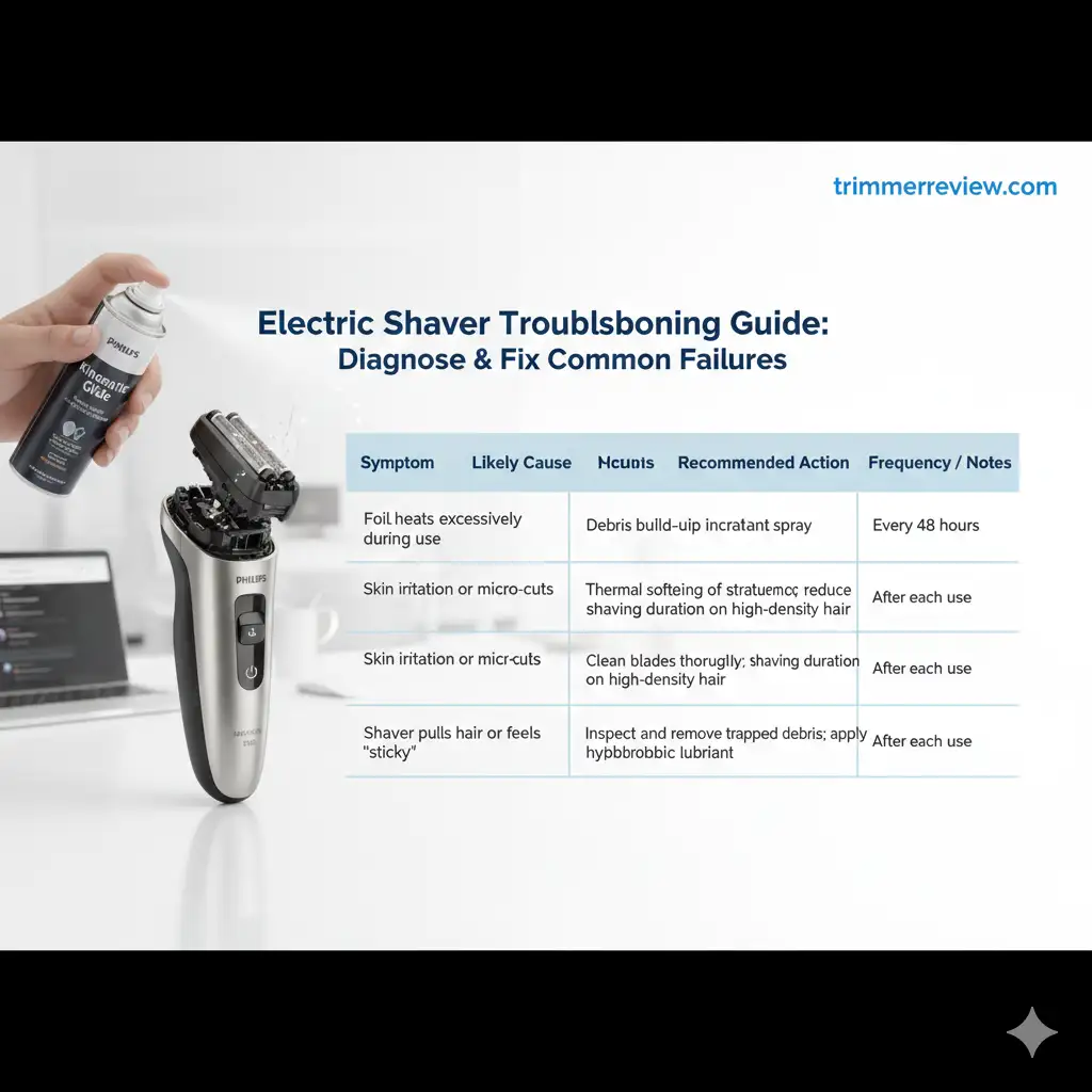
Symptom-Solution Matrix – Frictional Thermal Expansion
| Symptom | Likely Cause | Recommended Action | Frequency / Notes |
|---|---|---|---|
| Foil heats excessively during use | Debris build-up increasing friction | Apply dry lubricant spray | Every 48 hours |
| Skin irritation or micro-cuts | Thermal softening of stratum corneum | Clean blades thoroughly and reduce shaving duration on high-density hair | After each use |
| Shaver pulls hair or feels “sticky” | Foil-cutter interface friction increase | Inspect and remove trapped debris; apply hydrophobic lubricant | Weekly inspection recommended |
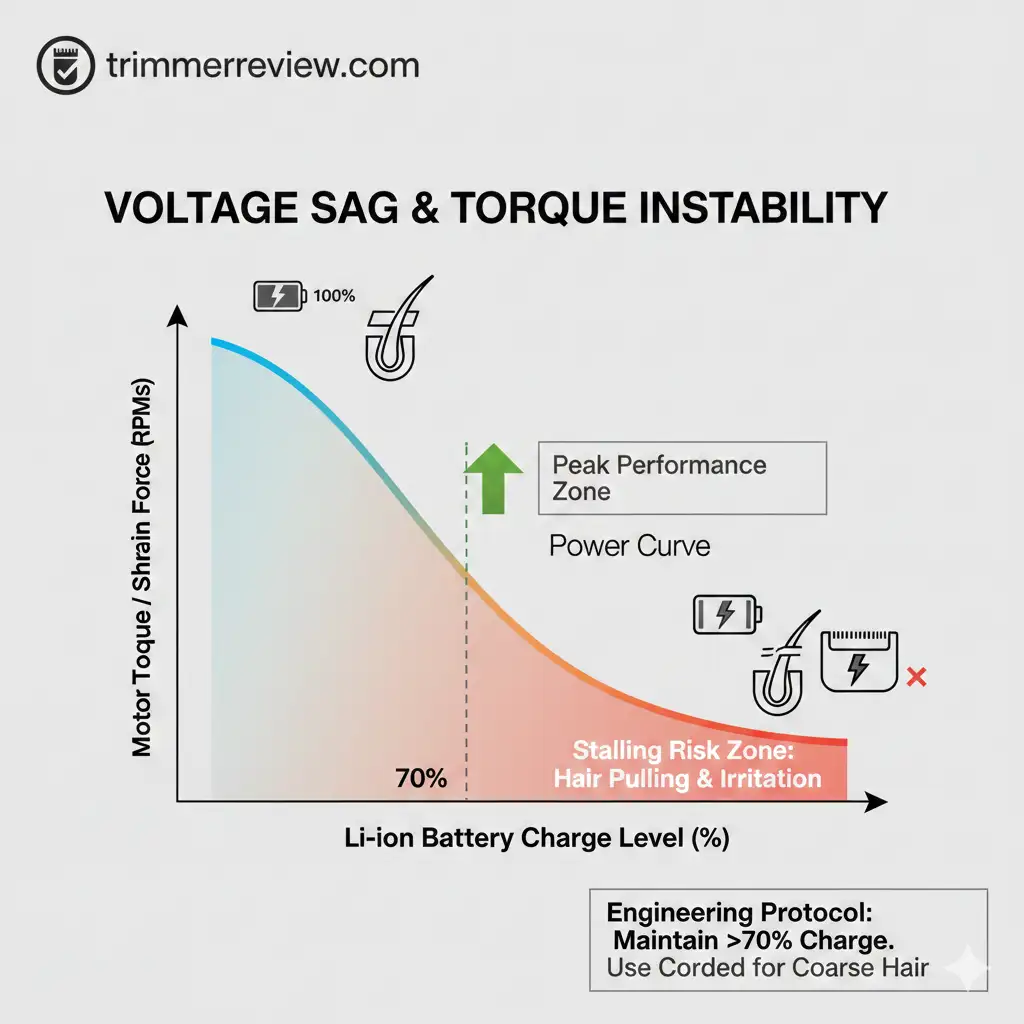
Voltage Sag and Torque Instability
A common misconception in the grooming industry is that hardware performance remains constant across the entire battery discharge cycle. In reality, most current-generation devices are susceptible to “Voltage Sag,” a phenomenon that often results in systemic electric shaver mechanical failure.
- The Power Curve: As lithium-ion cells deplete, the torque—the rotational force necessary for effective shearing—diminishes. This degradation in power frequently occurs even when the audible RPM remains deceptively consistent.
- The Mechanical Failure: When encountering dense terminal hair, a weakened motor fails to maintain sufficient shearing force. This results in the hair becoming wedged between the cutter and the foil membrane rather than being cleanly severed.
Engineering Protocol: To ensure the motor operates within its peak power band, hardware should be maintained at a charge level exceeding 70%. For high-density or coarse hair, corded operation is recommended to provide a consistent voltage supply and prevent torque-related failure.
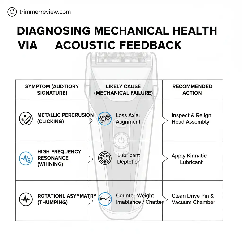
Diagnosing Mechanical Health via Acoustic Feedback
In high-precision grooming instruments, acoustic monitoring serves as a primary non-invasive diagnostic tool. Deviations from the standard operating frequency often signal the onset of electric shaver mechanical failure. Recognizing specific auditory signatures allows for the identification of internal component fatigue before it manifests as epidermal trauma.
- Metallic Percussion (Clicking): This signature indicates a loss of axial alignment between the cutter blade and the foil membrane. Misalignment compromises the shearing geometry, creating uneven pressure distribution and increasing the probability of epidermal nicks.
- High-Frequency Resonance (Whining): An elevated, sharp pitch is a characteristic indicator of lubricant depletion within the blade assembly. The subsequent metal-on-metal friction accelerates thermal transfer, causing the foil to exceed safe operating temperature thresholds.
- Rotational Asymmetry (Thumping): Rhythmic irregularities typically point to an imbalance in the internal counter-weights or drive shaft assembly. This mechanical instability produces “chatter”—micro-oscillations that result in localized post-shave irritation.
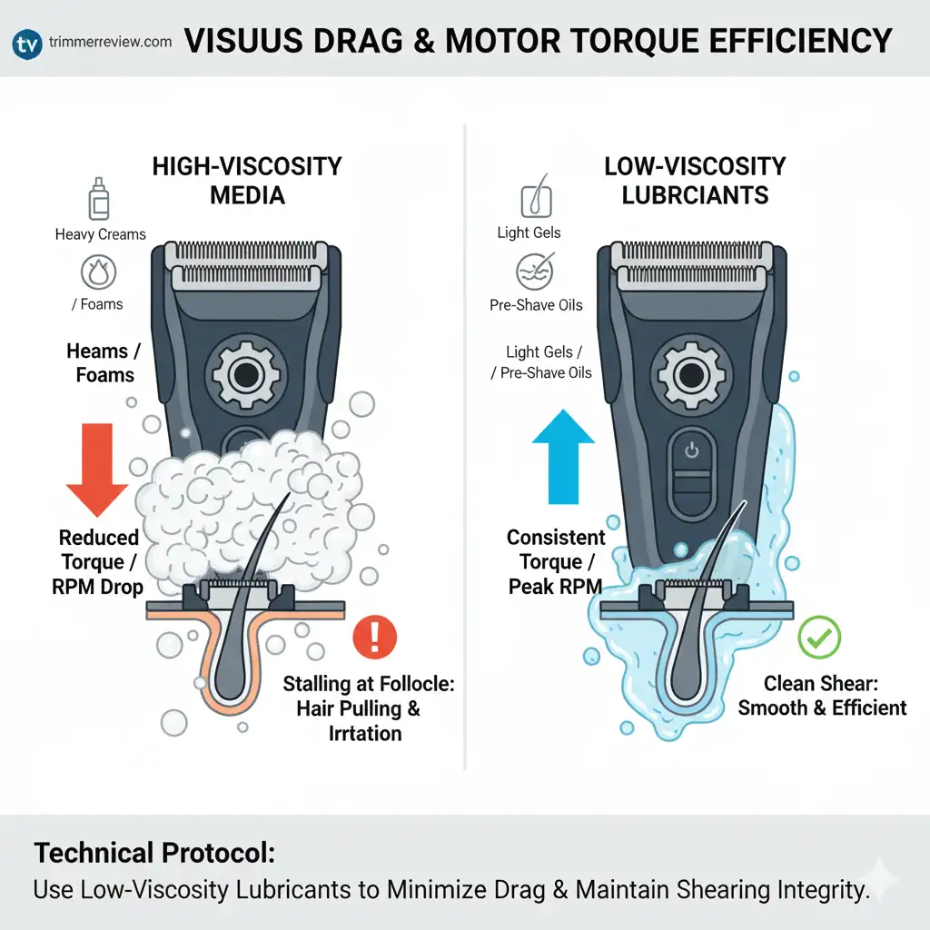
The Impact of Viscosity on Motor Torque
Current-generation electric shavers utilize high-velocity motors engineered for specific resistance thresholds. These systems are highly sensitive to “viscous drag,” a phenomenon where the fluid density of the shaving medium directly impacts electromechanical performance.
- The Impact of High-Viscosity Media: High-density foams and heavy creams impose a parasitic load on the motor assembly. This increased resistance causes a measurable decline in RPM and a corresponding drop in torque, forcing the device to operate below its intended power band.
- The Resulting Mechanical Failure: When torque output is insufficient to overcome the resistance of the hair and the medium, the blades fail to achieve the velocity required for a clean shear. This leads to “stalling” at the follicle interface, where hair is wedged into the apertures rather than severed, resulting in significant epidermal stress.
Technical Protocol: To maintain peak mechanical efficiency, the use of low-viscosity gels or specialized electric pre-shave lubricants is required. These formulations minimize drag, allowing the drive shaft to maintain consistent rotational speed and ensuring the integrity of the shearing action.
Material Science and Sensor Calibration
- Modern electric shavers operate as precision electromechanical systems where cutting performance depends not only on motor power but also on the microscopic integrity of the blade material and the accuracy of onboard sensor systems. The metallurgy of the cutting assembly determines how well the blade maintains its geometry under repeated high-speed oscillations, while the internal sensors regulate motor output based on resistance detected during shaving.
- When either of these elements deviates from its intended calibration, the efficiency of the shearing mechanism begins to decline. Blade wear gradually alters the cutting angle, and inaccurate sensor feedback can disrupt the balance between torque delivery and load resistance. Understanding these material and digital control factors helps maintain stable shaving performance and reduces the likelihood of mechanical stress that can lead to irritation or inconsistent cutting.
The Science of Blade Geometry: Micro-Rounding
Even blades labelled as “self-sharpening” will gradually lose their optimal edge due to normal wear. Understanding the mechanical implications of blade geometry helps prevent irritation and maintain cutting efficiency.
- Pressure Trap: As blades wear, the sharp “V”-shaped edge gradually rounds into a “U” shape. This requires greater down force during shaving, which can push skin deeper into foil perforations, increasing the risk of micro-cuts and discomfort.
- Replacement Protocol: To preserve consistent shearing performance, blade assemblies should be replaced based on accumulated motor runtime. Industry standards recommend replacing the shaver head every 40 hours of use.
Blade Geometry and Replacement Guidelines
| Blade Condition | Mechanical Impact | Biological Risk | Recommended Action |
|---|---|---|---|
| Sharp “V” edge | Optimal cutting with minimal pressure | Low risk of irritation | Normal maintenance |
| Rounded “U” edge | Increased down force required | Higher risk of micro-cuts and skin stress | Replace blade assembly |
| Excessive wear / chipped | Inefficient shearing, hair pulling | Moderate to severe skin trauma | Immediate replacement; inspect drive system |
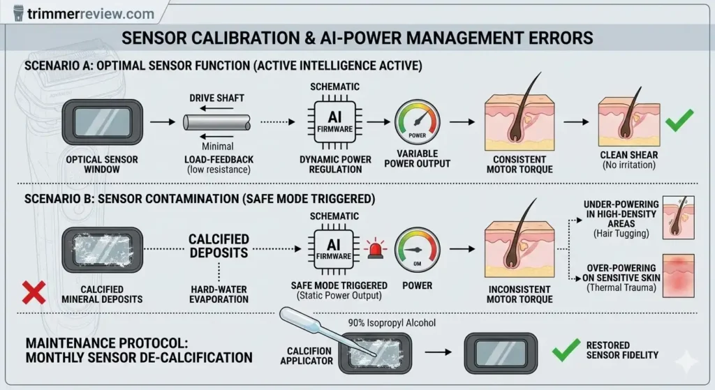
Sensor Calibration and AI-Power Management Errors
Modern grooming systems utilize “Active Intelligence” logic to dynamically regulate power based on real-time load feedback. The effectiveness of this system is entirely dependent on the optical or magnetic sensor window located near the drive shaft assembly. If this window is obscured by calcified mineral deposits—a common byproduct of hard-water evaporation—the firmware triggers a “Safe Mode” state.
This state represents a systemic electric shaver mechanical failure originating from the digital control layer. In “Safe Mode,” the processing unit defaults to a static power output because it can no longer interpret variable resistance. Consequently, the motor may under-power in high-density areas (leading to tugging) or over-power on sensitive skin (leading to thermal trauma).
Maintenance Protocol: Sustaining sensor fidelity requires a monthly de-calcification of the sensor window. Applying 90% isopropyl alcohol via a precision applicator removes mineral scaling, ensuring the “Active Intelligence” system maintains accurate data input and consistent motor regulation.
Drive System Integrity and Maintenance
- Counter-weight stability plays a critical role in maintaining smooth and controlled oscillation within the shaving head. In high-speed grooming devices, even a minor imbalance in the drive shaft assembly can amplify vibration patterns across the cutting interface. This mechanical disturbance interferes with the precise alignment between the cutter and foil, reducing cutting efficiency and increasing the likelihood of skin irritation.
- Over time, continuous high-RPM operation places stress on the internal balancing system. If the counter-weights shift slightly or encounter resistance from accumulated debris, the oscillation pattern becomes irregular. This instability alters the intended cutting trajectory, forcing the blades to interact with hair and skin at inconsistent angles. As a result, the shaving process may produce uneven cutting, localized pressure points, and a noticeable increase in operational noise.
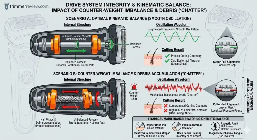
Counter-Weight Imbalance and “Chatter”
The drive shaft functions as a high-precision component, stabilized by calibrated counter-weights to maintain rotational or linear equilibrium. Sustaining this balance is critical for mitigating mechanical resonance—a primary precursor to electric shaver mechanical failure during high-velocity operation. When these internal harmonics exceed engineered limits, the resulting vibration causes “chatter,” a state of instability that accelerates component fatigue and marks the onset of systemic electric shaver mechanical failure.
- Mechanical Shift and Oscillation: Physical impact from dropping the device, or the progressive accumulation of internal debris, disrupts this rotational balance. This imbalance manifests as “chatter”—a high-frequency, erratic oscillation of the shaver head against the skin surface. Unlike standard vibration, chatter compromises the cutting geometry and increases the risk of epidermal abrasion.
- Acoustic Indicators of Fatigue: A shift toward a metallic or discordant vibration typically signals that the drive assembly is compromised. Such auditory changes indicate that the internal counter-weights are struggling against parasitic resistance from foreign matter.
Technical Maintenance: Periodic inspection of the drive pin is required to identify and remove “hair wraps”—fine strands that entwine around the rotating shaft, increasing frictional load. If acoustic irregularities persist, a vacuum clearing of the internal drive chamber is necessary to restore kinematic balance.
Note: Just like high-velocity shavers, smaller grooming tools also experience torque-related stress. Pulling or resistance in confined grooming areas may indicate nose trimmer mechanical fatigue, which follows similar kinematic principles.
The 2026 Restoration Protocol
To preserve factory-standard performance and mitigate the incidence of electric shaver mechanical failure, a structured maintenance protocol is mandatory for modern high-velocity oscillators. Consistent sanitization and kinematic lubrication ensure that internal drive components remain within their engineered tolerances. By minimizing parasitic drag and frictional resistance, this protocol prevents the systemic degradation typically associated with electric shaver mechanical failure, thereby maintaining stable torque delivery and peak shearing efficiency throughout the device’s lifecycle.
- Aqueous Flush: Rinsing the head assembly under water at approximately 40°C dissolves accumulated sebum before it hardens into obstructive debris.
- Degreasing: Periodically cleaning the cutters with a mild detergent removes residual oils that water alone cannot eliminate, maintaining optimal blade contact and cutting efficiency.
- Sterilization: Submerging the head in isopropyl alcohol for two minutes disinfects the assembly while promoting rapid evaporation of moisture, reducing the risk of bacterial growth.
- Kinematic Lubrication: A single drop of specialized machine oil applied to the drive pin reduces friction, ensuring full torque transfer from the motor to the blade assembly
2026 Maintenance Schedule for Hardware Longevity
| Maintenance Step | Purpose / Impact | Recommended Frequency |
|---|---|---|
| Aqueous Flush | Dissolves sebum and loose debris from the cutting assembly | After every use |
| Degreasing | Removes residual oils and buildup from cutters | Weekly |
| Sterilization | Disinfects the shaving head and promotes rapid moisture evaporation | Monthly |
| Kinematic Lubrication | Reduces mechanical friction and maintains consistent motor torque | Every 2–3 weeks |
Related Guides & Expert Resources
The following expert resources provide additional technical insights into grooming hardware performance, maintenance practices, and comparative device analysis. These guides expand on key topics related to motor efficiency, blade design, and long-term device reliability across different grooming tools. Reviewing these articles can help users better understand how similar mechanical principles apply to both electric shavers and precision trimmers, allowing for more informed maintenance decisions and improved grooming outcomes.
- Philips NT3650/16 Review (2026)
- Philips NT3650/16 vs Philips Norelco NT3600
- Philips Nose Trimmer Series 3000 vs 5000
- How to Use a Nose Trimmer (Step-by-Step)
Summary: Preventing Electric Shaver Mechanical Failure in 2026
Optimal shaving performance depends on maintaining the mechanical integrity of the device. Maintaining high-standard results requires a precise understanding of the interplay between motor torque, thermal expansion, and blade geometry.
By monitoring these variables, it becomes possible to identify the early indicators of electric shaver mechanical failure before they manifest as component degradation or epidermal trauma. Addressing these technical deviations through a structured maintenance protocol ensures that the shearing process remains within engineered specifications, effectively eliminating the root causes of procedural irritation.
Frequently Asked Questions (FAQs)
The following questions address some of the most common technical concerns related to electric shaver mechanical performance and maintenance. These answers clarify how internal components, motor torque stability, and blade wear influence shaving efficiency and skin comfort. By understanding these underlying mechanical principles, users can more easily diagnose performance issues and apply the appropriate maintenance protocols to preserve both device longevity and safe grooming results.
What are the primary causes of follicular traction (hair pulling)?
Follicular traction is typically symptomatic of torque instability. When the power source experiences “Voltage Sag” or the drive pin encounters parasitic drag from debris, the assembly fails to maintain the requisite shearing force. Maintaining a battery state-of-charge (SoC) above 70% ensures the motor operates within its peak power band, preventing hair from wedging between the cutter and the foil.
What determines the replacement cycle for cutting assemblies?
In accordance with 2026 hardware benchmarks, assemblies should undergo replacement at 40-hour operational intervals. Beyond this limit, the cutter undergoes “micro-rounding”—a specific electric shaver mechanical failure where the blade’s apex loses its engineered geometry. This degradation forces the user to increase manual pressure, leading to epidermal trauma.
What is the mechanism behind thermal escalation in the foil head?
Elevated temperatures are a direct result of frictional thermal expansion. The accumulation of lipids and keratinized cells increases the frictional coefficient between the cutter and the foil interface. The resulting heat transfer reduces the structural rigidity of the stratum corneum, leading to aperture-induced micro-lacerations. Utilizing a dry lubricant every 48 hours establishes a hydrophobic barrier to mitigate this thermal transfer.
Can sensor contamination induce systemic failure?
Yes. Obscured “Active Intelligence” sensors result in a digital logic failure. If mineral scaling blocks the sensor’s optical or magnetic window, the firmware cannot accurately modulate power. This creates a state of inconsistent motor output, where the device under-powers in high-density areas. Monthly de-calcification with 90% isopropyl alcohol is necessary to maintain sensor fidelity.
How is kinematic imbalance in the drive shaft identified?
Kinematic imbalance is identified by high-frequency “chatter” or discordant metallic resonance. This indicates that the internal counter-weights are no longer compensating for the mass of the assembly, often due to “hair wraps” around the drive pin. This imbalance causes the head to oscillate vertically against the skin rather than maintaining a consistent glide.
Transparency & Fact-Checking
For full transparency and product information verification details, refer to the Disclaimer & Fact-Checking Policy.